 |
F-16 LWFLight Weight Fighter |
Largest fighter program in the Western world
General Dynamics F-16 Fighting Falcon is one of most significant fighters of the latter part of the 20th century. It was originally developed from a concept for an experimental lightweight fighter and has evolved into an all-weather fighter and precision attack aircraft. The F-16 has been manufactured on as many as five separate production lines, making it the largest fighter program in the Western world. Over 4000 F-16s have been built, with production still continuing, making it the largest fighter program in the Western world.
The F-16 was the culmination of various studies and concepts, including the "Advanced Day Fighter" and the "Light-Weight Fighter". This article provides an overview of the background and origins of the F-16.
High-performance fighter studies : F-X and ADF
As early as 1965, the USAF had begun concept formulation studies of new high-performance fighters. These included the F-X, a heavy interceptor/air-superiority fighter, and the lightweight Advanced Day Fighter (ADF). The F-X was to be in the 40,000-pound class and was to be equipped with advanced, sophisticated radar's and armed with long-range, radar-guided air-to-air missiles. The ADF was to be in the 25,000-pound class and was to have a thrust-to-weight ratio and a wing loading intended to better the performance of the MiG-21 by at least 25 percent. The general concept behind the ADF was much the same as the reasoning which had led after the Korean War to the Lockheed F-104A Starfighter.
The appearance of the Mach 2.8-capable MiG-25 Foxbat in 1967 frightened Defense Department analysts and prompted a redirection in USAF fighter plans, with high performance once again becoming the primary concern. The F-X concept was eventually to emerge as the McDonnell Douglas F-15 Eagle, a twin-engined fighter with advanced avionics and long-range missiles. The ADF was temporarily shelved.
F-XX
The ADF concept was kept alive by former fighter instructor Major John Boyd and Pierre Sprey, a civilian working in the office of the Assistant Secretary of Defense for Systems Analysis. They both disliked the F-X concept as it then existed, and preferred a much simpler design. In the late 1960s, they came up with a 25,000 pound design designated F-XX, which was to be a dedicated air superiority fighter with a high endurance, minimal electronics, and no long-range missiles. Later studies brought this weight down to 17,000 pounds. The concept met with much opposition within the Air Force hierarchy, since some considered it a threat to the existing F-X project. However, the Pentagon decided to continue the project at a low level just in case the F-X (i.e. F-15) program got delayed or encountered serious developmental difficulties.
In 1969, a Pentagon memorandum suggested that both the Air Force and the Navy adopt the F-XX as a substitute for the F-15 and F-14 respectively, since both these planes were becoming increasingly expensive. Both services vigorously resisted these moves, and both the F-14 and F-15 surged ahead.
Pushing the concept
Deputy Defense Secretary David A. Packard (who came in with the new Nixon Administration in 1969) was a strong advocate of returning to the concept of competitive prototyping as a way of containing the ever-increasing costs of new weapons systems. During the 1960s, under Secretary of Defense Robert MacNamara, the Total Procurement Package philosophy had been adopted, in which an aircraft was committed to production even before the first example had flown and without any competitive flyoff against rival designs. This had led to such controversial aircraft as the Lockheed C-5A Galaxy and General Dynamics F-111, which had both encountered expensive and time-consuming developmental problems and extensive cost overruns.
Under the new competitive prototyping philosophy, Air Force Secretary Robert C. Seamans drew up a set of ground rules in which the initial funding of a new weapons project would be relatively limited, with initial performance goals and military specifications being kept to a minimum. By 1971, Boyd was working for the Air Force Prototype Study Group. He was able to push the concept at a time when the idea of competitive flyoffs was coming back into fashion.
Request For Proposals
A Light Weight Fighter (LWF) program came into being under Packard's watch. A Request For Proposals (RfP) was issued to the industry on January 16, 1971. The RFP called for a high thrust-to-weight ratio, a gross weight of less than 20,000 pounds, and high maneuverability. No attempt would be made to equal the performance of the MiG-25 Foxbat, the emphasis being placed instead on the most-likely conditions of future air combat--altitudes of 30,000-40,000 feet and speeds of Mach 0.6 to Mach 1.6.
Emphasis was to be on turn rate, acceleration, and range rather than on high speed. A small size was stressed, since the small size of MiG-17 and MiG-21 had made them difficult to detect visually during combat over North Vietnam. The RFP specified three main objectives. The aircraft should fully explore the advantages of emerging technologies, reduce the risk and uncertainties involved in full-scale development and production, and provide a variety of technological options to meet future military hardware needs.
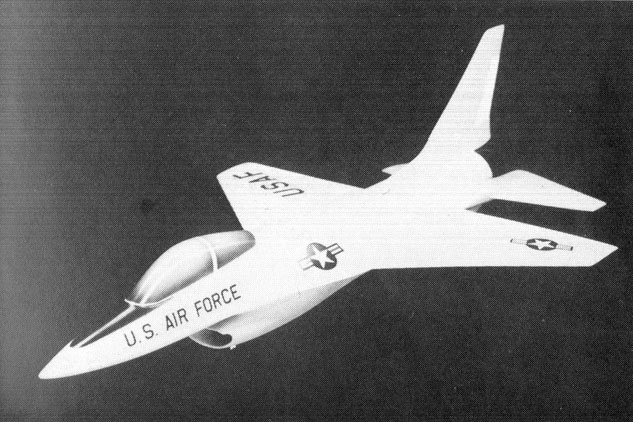
In the meantime, with the selection of the McDonnell Douglas F-15 Eagle as winner of the F-X contract, General Dynamics engineers had been concentrating on studies of a LWF for daytime dogfighting, with only minimal air-to-air electronics being provided. These studies had all been performed under the company designation of Model 401.
Proposals for the LXF
Five manufacturers submitted proposals in response to the RFP --- Boeing, Northrop, General Dynamics, Ling-Temco-Vought, and Lockheed. In March of 1972, the Air Staff concluded that the competing Boeing Model 908-909 was the first choice, with the General Dynamics Model 401 and the Northrop Model P-600 being rated as close seconds. The Vought V-1100 and Lockheed CL-1200 Lancer had been eliminated.
The Source Selection Authority, after further work, rated the General Dynamics and Northrop proposals ahead of the Boeing submission. The General Dynamics Model 401-16B and the Northrop P-600 were chosen for further development on April 13, 1972, and contracts for two YF-16s (#72-1567 and #72-1568) and two YF-17's (no. 72-1569 and no. 72-1570) were awarded. Rather than the "X" (experimental) prefix being used, the "Y" (development) prefix was used in order to indicate that a mixture of off-the-shelf and experimental technologies were being used. The YF-16 was to be powered by a single Pratt & Whitney F100 turbofan, whereas the YF-17 was to be powered by a pair of General Electric YJ101 engines.
The "cost plus fixed fee" contracts covered the design, construction, and testing of two prototypes, plus a year of flight testing. At the time, the Air Force was still very much committed to the F-15 fighter, and visualized the LWF program as more of a technology-demonstration project rather than a serious effort for a production aircraft. At the same time, contracts were given to Pratt & Whitney for a version of the F100 turbofan specially adapted for single-engined aircraft and to General Electric for the new and smaller YJ101 engine.
Keeping costs down
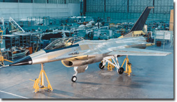
The YF-16 was designed and built at Fort Worth under the direction of William C. Dietz and Lyman C. Josephs, with Harry Hillaker as chief designer. The General Dynamics Model 401 had been studied in models, mockups, and wind tunnel testing dozens of different configurations before the final configuration was chosen. No attempt was made to push individual technological advances, with proven systems and components being used in areas where new technology was not required.
Components and detail assemblies were designed for ease of manufacture using low-cost conventional materials where possible. In order to keep costs down, many of the components were to have commonality with existing or projected aircraft. However, new technology was to be used in those situations where it would have the greatest effect in meeting performance goals.
General Dynamics decided to use a single F100 turbofan for their proposal rather than a pair of low-bypass GE YJ101s, which were used by the competing Northrop design. A single F100 was estimated to provide a substantially lower fuel demand than a pair of YJ101s, and studies revealed no significant attrition advantage for a twin-engine arrangement. The single-engined format made it possible to achieve a mission weight of 17,050 pounds, whereas a format powered by twin General Electric YJ101 engines would have had a mission weight of 21,470 pounds.
Early design development
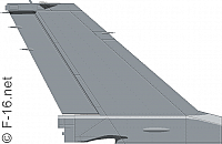
During the early design development of the F-16, General Dynamics had considered both single and twin vertical tails. Wind tunnel tests had showed that vortices produced by the forebody strake generally improved directional stability, but that certain strake shapes actually reduced stability at high angles of attack when twin tails were used. It was concluded that a twin-tail format would result in significantly greater development risks and that a single vertical tail would give satisfactory results provided that it was sufficiently tall.
The General Dynamics team also studied several different air intake configurations before settling on the final air intake located underneath the nose. The ventral location for the intake was chosen to minimize the sensitivity of airflow into the engine to high angles of attack. At a 20-degree AoA, the local flow direction to a ventral intake was only ten degrees below datum, as compared to 35 degrees in the case of side-mounted inlets.
The design team had actually started with a chin-mounted Crusader-type intake, but it was gradually pushed further and further back to save weight until the process finally had to be halted to keep the intake ahead of the nosewheel. There are some disadvantages to such an air intake location --- the mounting of the inlet underneath the fuselage is potentially dangerous to ground personnel and appears at first sight to invite foreign object damage (FOD) to the engine by the ingestion of stones and other runway debris into the intake. However, it avoids the gun gas ingestion problem, and since the nosewheel is further back, it avoids nosewheel-induced FOD. In order to save weight and complexity, the geometry of the intake was fixed.
Different wing planforms
Four different wing planforms -- straight, swept, variable, and delta -- were reviewed. The variable-geometry wing was rejected because of its high weight and complexity. The delta wing had the advantage of low weight per unit of area and low wave drag, but was ultimately rejected because of its high drag-at-lift and trim drag penalties. A low-sweep, straight wing was finally chosen because it was thought to offer the best combination of good maneuverability, high acceleration, and maximum lift to ensure good altitude performance. The team chose a computer-controlled variable camber wing with leading-edge maneuvering flaps and trailing-edge flaperons which could match the camber of the wing to flight conditions, thus maximizing wing efficiency.
The wing and main fuselage body were smoothly blended into each other in three dimensions, making it impossible to define where the wing ends and the fuselage begins. The blended wing-body, or lifting body effect is achieved by having a smooth fairing of the wing and fuselage rather than the conventional sharp intersection, providing improved lift at high angles of attack. The wing was fitted with smoothly-blended leading edge strakes. These strakes create vortices at high angles of attack which maintain the energy of the boundary layer air flowing over the inner section of the wing, delaying the stalling of the wing root and maintaining the directional stability.
Since the wing was far too thin to accommodate landing gear members, the main undercarriage was fuselage-mounted, with the wheels retracting into under-fuselage wells. The wing is made predominantly of aluminum, with small amounts of steel, titanium and composite materials.
Electronics
A "relaxed" static stability/fly-by-wire (RSS/FBW) control system was provided. A number of elements were added to aid the pilot in up to 9g combat. These included a side-stick console layout, an ejector seat tilted backwards by 30 degrees, and an all-round vision bubble canopy.
Although the LWF requirement specified only minimal electronics , the design team recognized that an operational aircraft would probably require a heavier and more bulky avionics package. The decision was made to size the aircraft to carry heat-seeking Sidewinder missiles plus an M61 cannon, but to make provisions to allow Sparrow radar-homing missiles to be carried at a later date should this be required.
The original specification had called for a load factor of 7.33 g while carrying 80 percent internal fuel. General Dynamics engineers decided to increase this figure to 9g at full internal fuel and to increase the service life of the airframe from 4000 hours to 8000 hours.
Recognizing that the YF-16 pilot would use externally-carried fuel on the outbound trip to the combat zone and then return on the internal fuel, the design team allocated internal fuel volume accordingly, reducing the airframe size and shaving 1470 pounds off the empty weight and reducing the loaded weight by 3300 pounds. By doing this, the turning rate could be increased by ten percent and acceleration by 30 percent.
Costs were reduced by using interchangeable left- and right-handed tailplanes and flaperons. Most of the undercarriage structure was also common to either side. Avionics were simple and armament consisted of one 20-mm M61A1 rotary cannon and two AIM-9 Sidewinder missiles on the wingtips, plus stores on two external hardpoints underneath each wing.
Please use this form to add any list any error or omissions you find in the above text.
Note: your comments will be displayed immediately on this page. If you wish to send a private comment to the webmasters, please use the Contact Us link.