 |
F-16 XLCranked-Arrow Wing |
History
In February of 1980, General Dynamics made a proposal for a Fighting Falcon version with a radically-modified wing shape, which was originally proposed for use on supersonic airliners. The project was known as SCAMP (Supersonic Cruise and Maneuvering Program) and later as F-16XL. The delta wing was to be of a cranked-arrow shape, with a total surface of 633 sq. ft. (more than double the area of the standard F-16 wing).
The research objectives included exploring innovative wing planform and camber shapes to provide efficient supersonic cruise performance while providing fighter-like transonic and supersonic turn agility. The design was intended to offer low drag at high subsonic or supersonic speeds without compromising low-speed maneuverability.
Structure & Avionics
The program was initially funded by the manufacturer, and involved conversion of two FSD F-16A's. In late 1980, the USAF and General Dynamics agreed on a cooperative test program, with the Air Force providing the third and fifth FSD F-16s (A-3 (#75-0747) and A-5 (#75-0749)) for modification into F-16XL prototypes.
The fuselage was lengthened with 56 inches (142 cm) to 54 feet 1.86 inches by 'inserting' 2 new fuselage sections at the junctions between the three main fuselage sub-assemblies: one 26 inch (66 cm) section was inserted at the rear split point, and a 30 inch (76 cm) section at the front one. However, the rear 26in section, was not a continuous segment from the bottom to the top. Below the wing, a 26 inch segment was inserted just aft of the main landing gear, above the wing the segment was still 26 inches long, but inserted 26 inches farther aft than the segment below the wing. This made the section look like a backward "Z". The fuselage lengthening enabled the tail section to be canted up 3 degrees, necessary to prevent the engine nozzle from striking the runway during take off and landing.
The XL has no ventral fins for the same reason, but evidently did not need them, since the XL stability characteristics are in general superior to that of the F-16.
The engine inlet was only affected by the rear lower fuselage 26in extension, since the 30in forward fuselage extension was applied to the upper fuselage only. As a result, the F-16XL engine inlet is 26in longer than on a standard F-16A.
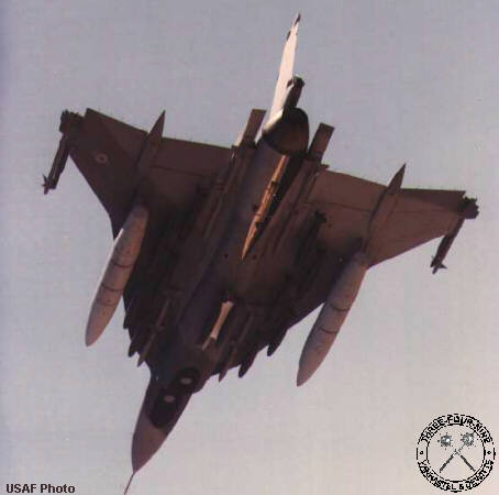
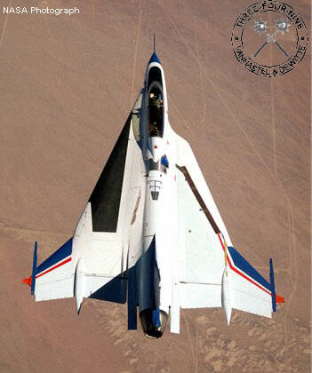
The wing planform was altered in a cranked-arrow delta wing (120% larger than the original F-16 wing), with extensive use of carbon composite materials (in the upper and lower layers of the skin) to save weight. Weight savings in the wings alone amounted to 600lbs. or 272kg. The wing is of multi-spar design with the leading edge sweep angle ranging from 50º to 70º, and is 2,800lbs (1,179 kg.) heavier than the original. The increase in internal volume (both by lengthening the fuselage and expanding the wing) allowed for a 82% increase in internal fuel capacity, while the increased wing area allowed the incorporation of up to 27 stores stations. Despite the apparent lengthening of the fuselage involved with the program, the new XL designation does NOT stand for "extra large".
Through wing planform improvements and camber optimizations, the final configuration offered a 25% improvement in maximum lift-to-drag ratio over the F-16 supersonically, and 11% improvement subsonic. The handling of the F-16XL was reportedly quite different from that of the standard F-16, offering a much smoother ride at high speeds and low altitudes. The configuration had matured into a very competent fighter with a large wing that allowed low-drag integration of large numbers of external weapons.
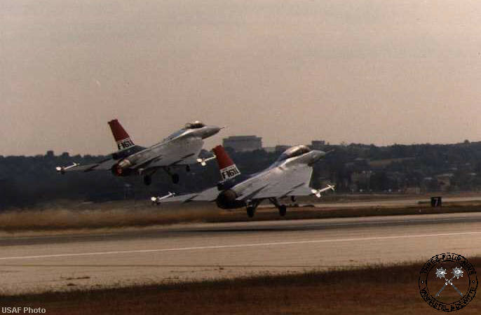
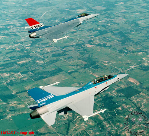
The first of two F-16XL's (#75-0749) to be modified, A-5 (5th Full-Scale Development F-16A) had a single seat and was powered by an F100-PW-200 turbofan. It flew for the first time on July 3rd, 1982, with James McKinney at the controls. The second F-16XL (#75-0747), was originally powered by a 29,000 lb.s.t. General Electric F110-GE-100 turbofan. It was converted from the 3rd FSD aircraft (A-3), which was severely damaged in a landing accident (nose tire failure) during the Edwards Open House in August of 1980. The aircraft took-off and blew it's nose tire in the event. The decision was taken to land with gears up. As soon as the nose gear touched down, it dug into the lake bed and snapped off. This caused the trailing edge of the radome , the leading edge of the forward equipment bay and the intale to carry the load. The intake scooped up tons of dry lake. In the process it was ground off on a line even with the forward bulkhead, (where the radar antenna hangs and the main gear tires). The radome was trashed and the equipment bay was ripped up. When this airframe arrived at Fort Worth for use in the XL program, it was accordingly missing the entire front end, and a new 2-seat front section was constructed for this aircraft. XL no. 2 flew for the first time on October 29th, 1982, piloted by Alex Wolf and Jim McKinney.
USAF Enhanced Tactical Fighter Program
In March of 1981, the USAF announced that it would be developing a new advanced tactical fighter. General Dynamics entered the F-16XL in the competition, the McDonnell Douglas company submitting an adaptation of the two-seat F-15B Eagle. Because of its increased internal fuel capacity and payload, the F-16XL could carry twice the payload of the F-16 and 40% further. The increased payload was carried on 27 hardpoints, which were arranged as follows:
- 16 wing weapons stations (750 lb capacity)
- 4 semi-submerged AIM-120 stations
- 2 wingtip stations
- 1 centerline station
- 2 wing "heavy / wet" stations
- 2 chin stations for LANTIRN
However, on each wing, the "heavy / wet" station was at the same buttline (distance from the center of the Fuselage) as two of the wing weapon stations. This means that you could use either the one " heavy / wet" or two weapon stations but not both at the same time.
Furthermore, if the "heavy / wet" station was used for an external fuel, the tank physically blocked one more wing station This meant that with external fuel tanks, the maximum number of weapons on the wings was 10. Two weapons could also be carried on a centerline adaptor. If no underwing fuel tanks were used, the maximum number of 500 lb class weapons was increased to 16. Although the XL could carry the centerline 300 tank, it was not really an operational loadout since mission range would actually be decreased unless the CL-300 could be dropped when empty.
In February of 1984, the Air Force announced that it had selected the McDonnell Douglas design in preference to the proposed production versions of F-16XL. The McDonnell Douglas proposal was later to enter production as the F-15E Strike Eagle. Had the F-16XL won the competition, production aircraft would have been designated F-16E (single-seat) and F-16F (two-seat). John G. Williams, lead engineer on the XL: "The XL is a marvelous airplane, but was a victim of the USAF wanting to continue to produce the F-15, which is understandable. Sometimes you win these political games, sometimes not. In most ways, the XL was superior to the F-15 as a ground attack airplane, but the F-15 was good enough."
Following the loss of the contract to MDD, General Dynamics returned both F-16XL's to Fort Worth during the summer of 1985 and placed them in storage. They had made 437 and 361 flights respectively, and although supersonic cruise without afterburner had been an original goal of the F-16XL program, the aircraft did never quite achieve this feat.
Modifications & Upgrades / NASA
In late 1988, the two prototypes were taken out of storage and turned over to NASA, where they received the serials #849 (A-5, ex #75-0749) and #848 (A-3, ex #75-0747). They were used in a program designed to evaluate aerodynamics concepts to improve wing airflow during sustained supersonic flight.
The first F-16XL, ship no. 1 was reflown on March 9, 1989 and delivered to the Ames-Dryden Flight Research Facility at Edwards AFB. This aircraft was modified for laminar-flow studies, with an experimental titanium section on its left wing (called a glove), with millions of tiny laser-cut holes (typical 2,500 holes/sq inch and 5 sq feet of holes).
Designed and built by Rockwell International's North American Aircraft Division (El Segundo, CA), its purpose was to siphon off (through active suction) a layer of turbulent surface air. This turbulent air layer, usually found on the wing's surface, affects flying performance by causing increased drag and fuel consumption. By removing the turbulent air layer, the laminar flow layer touches the wing's surface and far less drag is produced. Research by NASA to improve laminar flow dates back to 1926 when NASA's predecessor organization, the National Advisory Committee on Aeronautics (NACA), photographed airflow turbulence in a wind tunnel at its Langley Research Center, Hampton, VA. Smoke was ejected into the air stream and photographed as it showed visual signs of turbulence on the upper wing surfaces.
Early research such as this led to the eventual elimination of protruding rivet heads and other construction and design features that could create turbulence on high speed aircraft.
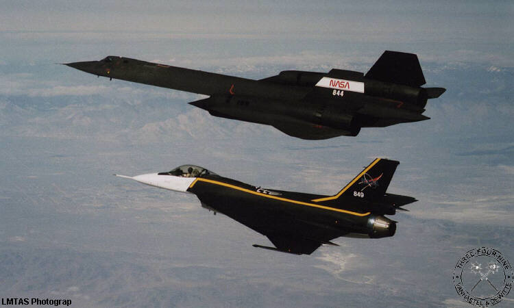
The first flight with the new wing took place on May 3rd, 1990, pilot Steve Ishmael at the controls. In January 1995 it performed a series of high-speed flights with NASA's SR-71. The aircraft were used to study the characteristics of sonic booms as part of the agency's high-speed civil transport program. Speed during these flights ranged from Mach 1.25 to Mach 1.8. During the flights, engineers recorded how sonic booms are affected by atmospheric conditions.
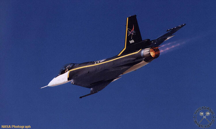
Later, ship no. 1 was transferred to NASA Langley, VA, where it was part of a flight test program for improving takeoff performance and reducing engine noise, and it was painted in an attractive high-viz black/yellow color scheme (with white front fuselage). The #849 went back to Edwards AFB by 1995, where it takes part in a sonic boom research project with an SR-71A.
The second F-16XL, ship no. 2, a two-seater, was delivered to NASA with a developmental engine that needed to be replaced before any flight testing could be done. NASA acquired a General Electric F110-129 engine through GD Ft. Worth, which provided surprisingly good performance. Supercruise was accidentally achieved in military power early on in the program; a speed of Mach 1.1 was achieved at 20,000 feet. A passive glove (foam and fiberglass fairing) was installed on the right wing in order to examine the aerodynamic fluid mechanics along the leading edge of a supersonic surface, noise environment, and pressure distribution. On the left wing, a new active glove was installed (double the size of ship no. 1's glove) consisting of a foam and fiberglass fairing around a test section of a high-tech composite with a porous titanium skin.
The glove has a maximum thickness of 2.5 inch, and covers 75% of the wing's surface and 60% of its leading edge. It was designed by a NASA-contractor team which included the Langley Research Center, Dryden, Rockwell International, Boeing, and McDonnell Douglas. The wing's S-Shaped blend was extended straight forward on the left side to match more closely the proposed wing for the high speed civil transport. The active section, the middle 66% of the glove, has at least 2,500 laser-drilled holes and is at least 10 sq feet large. The holes lead into 20 cavities beneath the wing's surface, which are used to control the suction at the wing's surface. The glove is chemically bonded to the skin itself with common epoxy resins. After the paint is removed from the aircraft, a couple of fiberglass layers are applied onto the skin of composite material, serving as protection for the skin when the glove is taken off again. Ship no. 2 is currently used as a testbed in the supersonic laminar-flow research project.
Specifications
Engine: One Pratt & Whitney F100-PW-200 turbofan (ship no. 1), rated at 12,240 lb.s.t. dry and 23,830 lb.s.t. with afterburning or one General Electric F110-GE-129 turbofan (ship no. 2), rated at 17,155 lb.s.t. dry and 28,984 lb.s.t. with afterburning
Maximum speed: Mach 1.8 (1,260 mph) for ship no 1 and Mach 2 (1,400 mph) for ship no. 2 at 40,000 feet. Service ceiling 50,000 feet. Maximum range 2850 miles. Initial climb rate 62,000 feet per minute.
Dimensions: wingspan 34 feet 3 inches, length 54 feet 2 inches, height 17 feet 7 inches, wing area 633 square feet.
Weights: around 22,000 pounds empty, 48,000 pounds maximum takeoff.
Special thanks
- Erwin Boone
- Tom Grindle
- John G. Williams
Please use this form to add any list any error or omissions you find in the above text.
Note: your comments will be displayed immediately on this page. If you wish to send a private comment to the webmasters, please use the Contact Us link.