Fighter Jet News
F-16 Fighting Falcon News
AFRL develops fixes to address JHMCS failures
December 17, 2008 (by
Mindy Cooper) -
Air Force and University of Dayton Research Institute engineers together have identified Joint Helmet Mounted Cueing System (JHMCS), display unit materials and processing issues and developed a repair capability for damaged systems.
Responding to high failure rates, the repairs are intended to return damaged units to service at substantial cost avoidance to the Air Force and Navy. In addition, implementation of recommended materials and processing changes by the original equipment manufacturer could potentially reduce or eliminate field failures of newly acquired assets.
Program managers for the system from Aeronautical Systems Center's 641st Aeronautical Systems Squadron asked Air Force Research Laboratory's Materials and Manufacturing Directorate engineers to determine if a repair capability could be developed to address failures to the helmet's electronic and optical display. Engineers were also asked to investigate the manufacturing process of display units to determine if any materials and processing practices were contributing to failures and whether particular changes to discovered materials and processing deficiencies may lead to a more rugged, robust system.
By developing a method to repair currently damaged assets, engineers said they have eliminated the need to replace damaged systems, estimated at $60,000 per unit. With the current number of damaged assets, a repair cost of only $1,000 per unit translates into a cost avoidance of $18 million. Just as important, the engineered fix prevents a JHMCS display unit shortage.
According to AFRL's Erik Ripberger, the materials research engineer managing the program, military fighter pilots wear HGU-55/P helmets modified with a JHMCS. The JHMCS display unit allows the pilot to look at a selected target, lock on, and engage.
"This system projects visual targeting and aircraft performance information on the display unit's visor, enabling the pilot to monitor this information without interrupting his field of view, effectively increasing the pilot's situational awareness," Mr. Ripberger said. "The visor is also critical for face and eye protection in the event of an ejection.
"Because the performance of the system is so crucial to the pilot's safety and mission, it is imperative that the structural integrity of every display unit is maintained," he continued. "Since no repair capability previously existed, any damaged display units were categorized as beyond economical repair and taken out of service. Due to the high failure rate of these systems, the Air Force and Navy are suffering a shortage of display units."
Most in-service damage occurs to the Relay Optics Mount Assembly, a composite shell that houses all electronic and optical components of the display units. The Relay Optics Mount Assembly consists of inner and outer composite shells, each fabricated from two layers of carbon fiber fabric infused with epoxy resin. The inner and outer shells are adhesively bonded to form the Relay Optics Mount Assembly.
Four locations on the Relay Optics Mount Assembly, the left and right bumps as well as the left and right visor mount bushings, are incurring the most damage. The left and right bumps, located at the top, aft portion of the Relay Optics Mount Assembly, are areas which sustain significant impact damage as a result of pilots striking their helmet on the canopy and canopy frames during flight maneuvers. The visor mount bushings secure the visor to the display unit while allowing the visor to pivot up and down over the pilot's face. The visor mount bushings are mounted to the Relay Optics Mount Assembly at the visor bushing mounts. Although not completely understood, engineers believe bushing damage is associated with load transferred to the bushing area during impacts or helmet donning/doffing.
During visits to manufacturer sites where display units are constructed, engineers observed that each shell making up the Relay Optics Mount Assembly is constructed from a loosely woven carbon fiber fabric. When the fabric is laid over the Relay Optics Mount Assembly tooling, spreading of fabric occurs in the bump areas, resulting in weak resin-rich regions. Adding to that problem was the method used to prepare the surface of the inner and outer Relay Optics Mount Assembly shells for bonding. This was done by grit blasting using blast media approximately 20 times larger than media currently implemented by AFRL engineers for composite surface preparation. This large blast media, used with identical blasting parameters as employed by the Materials and Manufacturing Directorate for the smaller media, erodes the composite shells causing a reduction in shell thickness. The fiber splaying and reduction in shell thickness severely weaken the strength of the Relay Optics Mount Assembly in the bump areas. In preparation for painting, the outer mold line of the Relay Optics Mount Assembly is hand sanded further reducing the thickness of the Relay Optics Mount Assembly shell.
"It is beneficial to maximize bond surface area when bonding two components together. The visor bushings are mounted adjacent to hollow stiffener channels which terminate at the visor bushing mount holes. The stiffener channels run from left to right along the ROMA shell to stiffen the display unit and add rigidity along that axis," explained Mr. Ripberger "Since the stiffener channels are hollow, the visor bushing mount bond surface area is significantly reduced. In addition, application of adhesive to the visor bushing and visor bushing mount bond surfaces is performed in a way that leads to inadequate wet-out of the bond surfaces. Finally, the surfaces of the visor bushing and visor bushing mounts are inadequately prepared."
Supported by laboratory testing, engineers recommended several key display unit manufacturing materials and processing changes. First, they recommended the manufacturer change the carbon fiber fabric style to a tighter weave and modify the orientation in which it is laid over the tooling to reduce or eliminate splaying in the bump areas. Second, engineers suggested the grit blast media used by the manufacturer be replaced with the Materials and Manufacturing Directorate recommended media to prevent Relay Optics Mount Assembly shell thinning during blasting operations. Third, engineers recommended the manufacturer incorporate Materials and Manufacturing Directorate standard best bonding practices coupled with a more comprehensive method for applying adhesive to and preparing the surfaces of the visor bushing and visor bushing mount bond surfaces. Lastly, engineers recommended a Relay Optics Mount Assembly visor bushing mount design change which would significantly increase the visor bushing mount bond surface area.
Engineers documented and delivered all materials and processing recommendations and repair processes to the 641st AESS program office. The program office is currently leveraging AFRL's findings to influence the manufacturer to change several of their materials and processing practices.
Engineers worked extensively with the Naval Surface Warfare Center, Crane Division located in Crane, Indiana, to effectively transition the repair technology. Engineers ensured Crane personnel were familiar with all aspects of the manufacture and installation of the doublers and ensured the readiness of their facilities to complete the associated tasks. The repair process has been fully implemented at the Naval Surface Warfare Center. Crane personnel have repaired their first 10 display units which will be returned to the field by the end of 2008 and are readying to complete the next 100 display unit repairs.
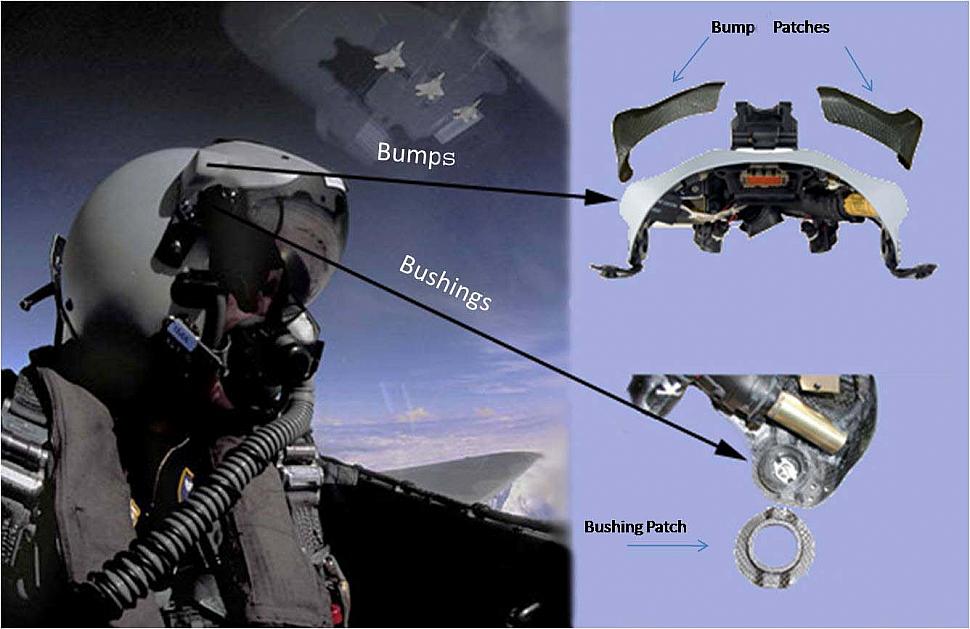
A fighter pilot wearing a Joint Helmet Mounted Cueing System is shown on the left. Helmet repairs developed by Air Force Research Laboratory engineers at Wright-Patterson Air Force Base, Ohio, are shown on the right. [USAF graphic]
Program managers for the system from Aeronautical Systems Center's 641st Aeronautical Systems Squadron asked Air Force Research Laboratory's Materials and Manufacturing Directorate engineers to determine if a repair capability could be developed to address failures to the helmet's electronic and optical display. Engineers were also asked to investigate the manufacturing process of display units to determine if any materials and processing practices were contributing to failures and whether particular changes to discovered materials and processing deficiencies may lead to a more rugged, robust system.
By developing a method to repair currently damaged assets, engineers said they have eliminated the need to replace damaged systems, estimated at $60,000 per unit. With the current number of damaged assets, a repair cost of only $1,000 per unit translates into a cost avoidance of $18 million. Just as important, the engineered fix prevents a JHMCS display unit shortage.
According to AFRL's Erik Ripberger, the materials research engineer managing the program, military fighter pilots wear HGU-55/P helmets modified with a JHMCS. The JHMCS display unit allows the pilot to look at a selected target, lock on, and engage.
"This system projects visual targeting and aircraft performance information on the display unit's visor, enabling the pilot to monitor this information without interrupting his field of view, effectively increasing the pilot's situational awareness," Mr. Ripberger said. "The visor is also critical for face and eye protection in the event of an ejection.
"Because the performance of the system is so crucial to the pilot's safety and mission, it is imperative that the structural integrity of every display unit is maintained," he continued. "Since no repair capability previously existed, any damaged display units were categorized as beyond economical repair and taken out of service. Due to the high failure rate of these systems, the Air Force and Navy are suffering a shortage of display units."
Most in-service damage occurs to the Relay Optics Mount Assembly, a composite shell that houses all electronic and optical components of the display units. The Relay Optics Mount Assembly consists of inner and outer composite shells, each fabricated from two layers of carbon fiber fabric infused with epoxy resin. The inner and outer shells are adhesively bonded to form the Relay Optics Mount Assembly.
Four locations on the Relay Optics Mount Assembly, the left and right bumps as well as the left and right visor mount bushings, are incurring the most damage. The left and right bumps, located at the top, aft portion of the Relay Optics Mount Assembly, are areas which sustain significant impact damage as a result of pilots striking their helmet on the canopy and canopy frames during flight maneuvers. The visor mount bushings secure the visor to the display unit while allowing the visor to pivot up and down over the pilot's face. The visor mount bushings are mounted to the Relay Optics Mount Assembly at the visor bushing mounts. Although not completely understood, engineers believe bushing damage is associated with load transferred to the bushing area during impacts or helmet donning/doffing.
During visits to manufacturer sites where display units are constructed, engineers observed that each shell making up the Relay Optics Mount Assembly is constructed from a loosely woven carbon fiber fabric. When the fabric is laid over the Relay Optics Mount Assembly tooling, spreading of fabric occurs in the bump areas, resulting in weak resin-rich regions. Adding to that problem was the method used to prepare the surface of the inner and outer Relay Optics Mount Assembly shells for bonding. This was done by grit blasting using blast media approximately 20 times larger than media currently implemented by AFRL engineers for composite surface preparation. This large blast media, used with identical blasting parameters as employed by the Materials and Manufacturing Directorate for the smaller media, erodes the composite shells causing a reduction in shell thickness. The fiber splaying and reduction in shell thickness severely weaken the strength of the Relay Optics Mount Assembly in the bump areas. In preparation for painting, the outer mold line of the Relay Optics Mount Assembly is hand sanded further reducing the thickness of the Relay Optics Mount Assembly shell.
"It is beneficial to maximize bond surface area when bonding two components together. The visor bushings are mounted adjacent to hollow stiffener channels which terminate at the visor bushing mount holes. The stiffener channels run from left to right along the ROMA shell to stiffen the display unit and add rigidity along that axis," explained Mr. Ripberger "Since the stiffener channels are hollow, the visor bushing mount bond surface area is significantly reduced. In addition, application of adhesive to the visor bushing and visor bushing mount bond surfaces is performed in a way that leads to inadequate wet-out of the bond surfaces. Finally, the surfaces of the visor bushing and visor bushing mounts are inadequately prepared."
Supported by laboratory testing, engineers recommended several key display unit manufacturing materials and processing changes. First, they recommended the manufacturer change the carbon fiber fabric style to a tighter weave and modify the orientation in which it is laid over the tooling to reduce or eliminate splaying in the bump areas. Second, engineers suggested the grit blast media used by the manufacturer be replaced with the Materials and Manufacturing Directorate recommended media to prevent Relay Optics Mount Assembly shell thinning during blasting operations. Third, engineers recommended the manufacturer incorporate Materials and Manufacturing Directorate standard best bonding practices coupled with a more comprehensive method for applying adhesive to and preparing the surfaces of the visor bushing and visor bushing mount bond surfaces. Lastly, engineers recommended a Relay Optics Mount Assembly visor bushing mount design change which would significantly increase the visor bushing mount bond surface area.
Engineers documented and delivered all materials and processing recommendations and repair processes to the 641st AESS program office. The program office is currently leveraging AFRL's findings to influence the manufacturer to change several of their materials and processing practices.
Engineers worked extensively with the Naval Surface Warfare Center, Crane Division located in Crane, Indiana, to effectively transition the repair technology. Engineers ensured Crane personnel were familiar with all aspects of the manufacture and installation of the doublers and ensured the readiness of their facilities to complete the associated tasks. The repair process has been fully implemented at the Naval Surface Warfare Center. Crane personnel have repaired their first 10 display units which will be returned to the field by the end of 2008 and are readying to complete the next 100 display unit repairs.
Courtesy of Materials and Manufacturing Directorate, Air Force Materiel Command.
Related articles:
Forum discussion:
Tags
- Wolf Pack AFE techs upgrade pilot equipment (2007-11-04)
- 18th FS 'Blue Foxes' receive JHMCS helmets (2007-03-03)
- F-16 Fighting Falcon news archive
Forum discussion:
- Start a discussion about this article in the F-16.net forum.
Tags