UK MOD in a muddle over F-35C
-

- Elite 5K

- Posts: 28404
- Joined: 05 May 2009, 21:31
- Location: Australia
Not sure what you are driving at with comments about lights on QE. They have a specialist lighting setup posted about on this very forum somewhere or tuther. Long exposure does weird things especially when subjects move - even ever so slightly, whilst night film/night camera settings enhance non-daylight settings for obvious reasons. Anyhoo, not to worry.
And what was the subject focus? Probably foreground but everything blurry with longer exposure. Zoom in on jpg below.
Apparently a lot of CVF deck lighting is LED (Light Emitting Diode) so that may skew fillum results also. Search this thread alone for LIGHTING to be surprised or not at how many times the name is MISS SPELLUD.
- Attachments
-
Last edited by spazsinbad on 03 Oct 2018, 04:29, edited 2 times in total.
-

- Elite 1K

- Posts: 1870
- Joined: 31 Dec 2015, 05:35
- Location: Australia
spazsinbad wrote:Not sure what you are driving at with comments about lights on QE. They have a specialist lighting setup posted about on this very forum somewhere or tuther.
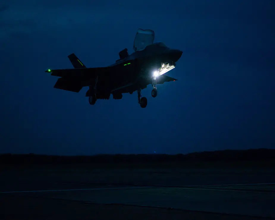
I figured the violet light was artistic illumination. I see a violet light illuminating the underside of the left wing of the the hovering aircraft, coming from the port side lower, as well. It looks like staging lights for a photo-op (to me).
Btw, the bright sky appears to be just a histogram-stretched moon light.
Accel + Alt + VLO + DAS + MDF + Radial Distance = LIFE . . . Always choose Stealth
-
- Elite 5K
- Posts: 28404
- Joined: 05 May 2009, 21:31
- Location: Australia
oops missed your post - have just 'feature updated Windows 10' and it is giving me the CREATURE FEATURES alright...
The zoom of the VLing F-35B has just been zoomed from above JPG with no other alteration. I would suggest the colours you see are those reflected from the NAV lights & whatever colour vision you may have (an unique attribute apparently).
Who knows what post processing has occurred. However just see the image for what it is - BEEYOOtiful NO?
OOHH and I forgot. How are YOU viewing this photo? Computer screens vary widely for colour / balance and all that tripe. Then throw in your operating system with whatever colour setting you have selected/changed and your UNCLE IS BOB!
- Attachments
-
Last edited by spazsinbad on 03 Oct 2018, 04:44, edited 1 time in total.
-
- Elite 1K
- Posts: 1870
- Joined: 31 Dec 2015, 05:35
- Location: Australia
You can see the violet on the white lift fan door's interior and also on the inside right horizontal stab. I just checked and it has been stretched.
Accel + Alt + VLO + DAS + MDF + Radial Distance = LIFE . . . Always choose Stealth
-
- Elite 5K
- Posts: 28404
- Joined: 05 May 2009, 21:31
- Location: Australia
Can't keep up with the comments. Whatever. My points still stand and you can claim what you claim. Who knows. Meanwhile this PDF (a repeat) is what I was looking for: https://www.consolite.co.uk/Technology/ ... R%20DH.pdf
Mentioned here earlier: viewtopic.php?f=58&t=15969&p=397699&hilit=Consolite#p397699
Mentioned here earlier: viewtopic.php?f=58&t=15969&p=397699&hilit=Consolite#p397699
"...HMS Illustrious was modified with a similar but more complete fit, and Ark Royal later brought up to the same standard. “For example, the deck status lights [‘traffic lights’] were replaced by LED arrays supplied by LFD Ltd. A number of flight trials have now been made on both ships, and after a few tweaks, the conversions are accepted and well liked by aircrew. Just as importantly, the availability of plenty of light on the deck, even during NVG operations, means that the deck crew can perform their duties without the constraints or danger of having to work, literally, in the dark.”
Consolite has gone on to modify a number of other ships for both the RN and other nations, including frigates, destroyers and LPDs, as well as landing craft so that the Marines can navigate them while using NVG, Rice reports. The company is now engaged in drafting a new specification for NVG lighting on warships, with particular reference to the new CVF class...."
-
- Elite 1K
- Posts: 1870
- Joined: 31 Dec 2015, 05:35
- Location: Australia
spazsinbad wrote:Can't keep up with the comments. Whatever. My points still stand and you can claim what you claim. Who knows.
Huh? "claiming" what? Just observing what Steve has said, as a part of the conversation.

Accel + Alt + VLO + DAS + MDF + Radial Distance = LIFE . . . Always choose Stealth
-
- Elite 5K
- Posts: 28404
- Joined: 05 May 2009, 21:31
- Location: Australia
OK. I'll claim this. People separated by time and space viewing the same JPG on a computer screen have NO CHANCE to see the same colours (if they both have the same colour vision which is not likely I claim). This is just how it is. You see things that others will not see for many reasons that have been referred to vaguely in my claims. You seem to 'claim' nusink. Are you OK with my claims?

-
- Elite 5K
- Posts: 28404
- Joined: 05 May 2009, 21:31
- Location: Australia
Heheh. Photos lie in any case: an image created by a mechanism then recreated by another mechanism for our eye to see.
-
- Elite 5K
- Posts: 28404
- Joined: 05 May 2009, 21:31
- Location: Australia
steve2267 wrote:popcorn wrote:Takeoff looks like it's in slow motion, that liftfan really gets the job done.
If I'm not mistaken, the Bee is lifting off in something like ~250ft -- about five aircraft lengths!?! Very impressive.
Since they are aviation-centric, I still think the USMC might do better with ramps on the LHA-6 USS America and LHA-7 USS Tripoli.
The Brits with their ramps and SRVL recoveries are on to something.
On previous page the STO FLYCO view is incorrectly captioned. I'll ask ON THE ROGER to change it, providing PHOTO. The 300 foot marker may be seen very briefly at start of video with the nosewheel of the BEE on the 350 foot marker as per:
https://www.savetheroyalnavy.org/wp-con ... lantic.jpg [view from bridge]
- Attachments
-
-
-
- Elite 5K
- Posts: 28404
- Joined: 05 May 2009, 21:31
- Location: Australia
Please make a drawing on a ship with the SAFE HEIGHT ABOVE SEA LEVEL. What kind of aircraft will use this 'madrat ramp'?
'ENGINES' aka Steve George ex-RN Aircraft Engineer on F-35B program on pPrune:
I'll stop the quotes there because there are many others which can be seen in a 'ski jump PDF' of many pages posted to this very forum somewhere.... SKI JUMP INFO VARIOUS Jun 2015 pp151.pdf (11Mb)
download/file.php?id=21005
I lied:
"...The uniqueness of the ski jump launch, Maack [Andrew Maack joined the F-35 program back in 1996 and has been the Pax River ITF Chief Test Engineer and Site Director since 2002] said, is that it enables the airplane to get more gross weight, more payload, more weapons and more fuel airborne off the bow of a ship. “In essence, the ramp provides vertical velocity in a ballistic fashion that enables the airplane to accelerate to flying speed at higher gross weights than you can off a flat deck," he noted...." http://www.navair.navy.mil/index.cfm?fu ... ry&id=6908
"...In place of the catapult, one innovation allowed the Sea Harrier to operate at higher weights from aircraft carriers. This was the “ski jump” ramp, an upwardly curved addition to the end of the flight deck runway that enabled the Sea Harrier to take-off at either lower airspeeds or at higher weights for a given deck run than a “flat deck” takeoff. The ramp also offered safety benefits, as it meant that the Sea Harrier should almost always be launched on an upwards trajectory even if the bows of the ship were pointing down, as often happened in heavy seas. Trials on land during the latter half of the 1970s proved the concept of the ramp, and showed that only relatively trivial modifications to the Sea Harrier’s undercarriage were required to allow it to use the new “ski jump” technique (Fozard, 1978; Davies & Thornborough, 1996)....
&
...Further benefits from previous experience with the Harrier, and studies into replacing it, are shown by the adoption of a “ski jump” ramp for take-off. Despite the fact that the CVF is much larger than the Invincible class and that the JSF has a completely different propulsion system, the ramp still gives the same benefits as it did on earlier ships: boosting capability by increasing payloads and enhancing safety, as well as freeing up more deck area for aircraft parking and recovery (Fry, 2008; Rolfe, 2008)...." http://acquisitionresearch.net/_files/F ... 09-010.pdf
'ENGINES' aka Steve George ex-RN Aircraft Engineer on F-35B program on pPrune:
"...A STOVL aircraft can launch at much higher relative weights, because it can vector its thrust to the optimum angle to support the aircraft by a combination of wing lift and powered lift so as to deliver the required acceleration and climb out. The angle will be scheduled after launch to move aft as wing lift builds. (Of note, the UK sets a minimum 400 fpm rate of climb as the limiting performance measure for ski jump launches).
Ski jump launch is an extremely effective system for maritime STOVL aircraft, is low workload and safe, as the pilot is guaranteed to be climbing away from the sea, and has more time to react in the event of an engine failure. It also delivers a large improvement in launch weight compared with a flat deck STO.
Oh, and the ski jump was a Royal Navy invention. And the F-35B lift system integration & flight controls design was led by some amazingly talented Brits. And Brits are leading the STOVL flight testing...." http://www.pprune.org/military-aircrew/ ... ost8450029
"...The second technique unforeseen when the Harrier was developed is the ski-jump take-off. Lt. Cdr. Doug Taylor, RN, first proposed this technique in 1973. It seems that his initial concern had been to make a rolling take-off safer on board ships, particularly on a pitching deck. In a large conventional carrier, pitching is quite moderate even in heavy seas. Moreover, a catapult launch is so fast that the flight deck officer can adjust his timing to the pitching of the ship and launch when the deck comes up so as to be sure not to "shoot" on a downwards trajectory. However, the Sea Harrier is designed to operate from relatively small ships, more sensitive to sea states and with shorter pitching periods, and when performing a rolling take-off from a downwards pitching deck it might come dangerously low over water. A ski-jump guarantees that regardless of the pitching angle the initial flight path will be upwards...." http://www.thefreelibrary.com/Short+tak ... -a08530123
“...In 1977 ski jump trials were carried out, initially from a land-based ramp that was adjustable from a 6 to 20 degree exit angle. This showed great improvements were possible with regard to performance, handling, safety and ship pitch motion limits when compared to flat deck ship STO's....” http://www.harrier.org.uk/history/history_farley.htm
"...page 9: “...The skeptics insist that ramps will displace landing spots. Tests prove otherwise. On a 12 degree ski jump approximately 150 feet long, the slope gradually increases from zero up to 12 degrees at the bow. The first half of the ski jump has a slope no greater than that of an LHA during wet-well operations with the well-deck flooded – both Harriers and helicopters can land on it...." [Major Art Nalls, USMC, "Why Don't We Have Any Ski Jumps," U.S. Naval Institute Proceedings, November 1990, 81.]
The ramp not only bolsters a STOVL aircraft’s combat payload to its maximum and enhances fixed- and rotary-wing interoperability, it provides a margin of safety to the pilot in emergency situations. The upward vector off the bow offers the pilot extra precious seconds to handle takeoff emergencies and an expanded ejection envelope if required. The price of one saved STOVL aircraft, and potentially the pilot’s life, would probably fund several ramps on amphibious ships. The Navy and Marine Corps need ski jumps on the big-deck amphibious ships....” http://www.dtic.mil/dtic/tr/fulltext/u2/a527872.pdf
"...Another important aspect of ski jump operations is the inherent safety over a flat deck launch, after which the aircraft is only 60 feet (height of the flight deck) above the water for the accelerating transition to airborne. With a ski jump, the Harrier ALWAYS has a positive rate of climb due to the incline of the ramp. The accelerating transition begins at approximately 150 to 200 feet, vice 60 feet [ASL]. This altitude cushion is a considerable increase in safety should the pilot encounter any emergency...." http://www.history.navy.mil/content/dam ... f/mj90.pdf
I'll stop the quotes there because there are many others which can be seen in a 'ski jump PDF' of many pages posted to this very forum somewhere.... SKI JUMP INFO VARIOUS Jun 2015 pp151.pdf (11Mb)
download/file.php?id=21005
I lied:
"......4.2 Safe launch metric [FOR THE F-35B aboard CVFs]
At the core of a ski jump performance analysis is the assessment of whether a launch case is achievable or not. The minimum safe launch is defined where the ramp exit speed does not result in any rate of descent during the trajectory until the aircraft has transitioned to fully wing-borne flight. This results in the launch profile shown in Fig. 8, with an inflection point at which the criteria for a successful launch are assessed.
There are two safe launch criteria derived from legacy STOVL experience that are used on the JSF program, of which the more stressing is adopted: (a) subtracting a margin from the WOD and requiring zero sink rate (known as Operational WOD); and (b) using the full value of WOD but requiring a defined positive rate of climb. Both also require a threshold forward acceleration....” http://www.raes.org.uk/pdfs/3324_COLOUR.pdf OR http://www.scribd.com/doc/190161709/CVF ... 324-COLOUR
- Attachments
-
Last edited by spazsinbad on 03 Oct 2018, 15:38, edited 6 times in total.
-
- Elite 1K
- Posts: 1870
- Joined: 31 Dec 2015, 05:35
- Location: Australia
Accel + Alt + VLO + DAS + MDF + Radial Distance = LIFE . . . Always choose Stealth
-
- Elite 5K
- Posts: 28404
- Joined: 05 May 2009, 21:31
- Location: Australia
Interesting tidbit dit about VLing the F-35B with weapon bay doors opening only just before touch down by Steve George.
Info on the F-35B STOVL flight controls
01 Oct 2018 'Engines' [Steve George]
"Going back to the start of the programme, the customers were very focussed on reducing through life cost and enhancing safety. The lessons of the USMC AV-8A fleet and the UK's Harrier experience were uppermost in their minds. They were also looking at reducing the pilot's flying workload as much as possible to allow him/her to focus on managing and winning in combat. They also wanted an aircraft that required less pilot training. These desires all came together in looking very hard at how to best control a STOVL aircraft in the transition, takeoff and landing.
These were crystallised out in the JORD in two ways. First, they demanded very good handling characteristics. secondly, they mandated that the flying controls that were operated by hand had to be limited to two 'inceptors'. The led to many studies and trials, and out of these came the F-35B system. I should note the huge contributions made by the BAE STOVL test pilots throughout the early years of the programme - their inputs, suggestions, criticisms and teamwork laid the foundation for what the team has achieved. A special mention should also go to the pioneering VAAC Harrier test bed, designed at Cranfield and put to hard work at Boscombe and also at sea, helping to develop the new STOVL flight control laws. It should be understood that two of the highest risk areas of the F-35 development programme were the integration of the STOVL propulsion system with the airframe, and the development of the STOVL flight control laws and flight control system. Both of these were led and executed by BAE Systems. Personally, I don't think they get anywhere near the amount of credit they are due.
The end result is a 'powered flight mode', which the pilot selects by a single action switch on the left hand 'inceptor'. This initiates the change from fully wing borne flight, and it can be selected over quite a wide speed range. In this mode, as I've posted earlier, the controls change from a 'throttle' (more like an energy demand) and 'stick' (more of a flight path demand) to a 'fore and aft rate' demand via the left hand inceptor, and a vertical rate and lateral rate demand via the right hand inceptor. This was a very controversial decision at the time, but was supported by extensive work in both conventional sims and the vertical motion simulator at NASA Ames, I believe. One aspect of this new flight control system is that the pitch of the aircraft is not controlled by the pilot.
However, the transition from 'normal wing borne' to 'full stop powered lift' is managed via an automated 'blend' programme which, I understand, is mainly driven by aircraft airspeed. So, the excellent pictures Gums posted up very probably (alert - I'm now assuming stuff) show an F-35B in the high speed end of the 'powered lift' mode. The landing gear is still up (this is selected independently from the powered lift mode selection), the lift fan door is in the 30 degree position for higher speeds, and the 3BSM is down at around 10 to 15 degrees or so. All the various doors are opened at this stage, except the inner weapon bay doors that deploy automatically just before touch down. In the powered lift mode, thrust can be moved between the front lift fan and the aft nozzle - it's not a fixed 50/50 spilt. So, in these pics, the lift fan IGVs will have shut down, reducing the power demand from the fan, and allowing more 'grunt' to come out of the rear....”
Source: https://www.pprune.org/military-aviatio ... st10263295
- Elite 3K

- Posts: 3901
- Joined: 16 Feb 2011, 01:30
spazsinbad wrote:Interesting tidbit dit about VLing the F-35B with weapon bay doors opening only just before touch down by Steve George.Info on the F-35B STOVL flight controls
01 Oct 2018 'Engines' [Steve George]
"Going back to the start of the programme, the customers were very focussed on reducing through life cost and enhancing safety. The lessons of the USMC AV-8A fleet and the UK's Harrier experience were uppermost in their minds. They were also looking at reducing the pilot's flying workload as much as possible to allow him/her to focus on managing and winning in combat. They also wanted an aircraft that required less pilot training. These desires all came together in looking very hard at how to best control a STOVL aircraft in the transition, takeoff and landing.
These were crystallised out in the JORD in two ways. First, they demanded very good handling characteristics. secondly, they mandated that the flying controls that were operated by hand had to be limited to two 'inceptors'. The led to many studies and trials, and out of these came the F-35B system. I should note the huge contributions made by the BAE STOVL test pilots throughout the early years of the programme - their inputs, suggestions, criticisms and teamwork laid the foundation for what the team has achieved. A special mention should also go to the pioneering VAAC Harrier test bed, designed at Cranfield and put to hard work at Boscombe and also at sea, helping to develop the new STOVL flight control laws. It should be understood that two of the highest risk areas of the F-35 development programme were the integration of the STOVL propulsion system with the airframe, and the development of the STOVL flight control laws and flight control system. Both of these were led and executed by BAE Systems. Personally, I don't think they get anywhere near the amount of credit they are due.
The end result is a 'powered flight mode', which the pilot selects by a single action switch on the left hand 'inceptor'. This initiates the change from fully wing borne flight, and it can be selected over quite a wide speed range. In this mode, as I've posted earlier, the controls change from a 'throttle' (more like an energy demand) and 'stick' (more of a flight path demand) to a 'fore and aft rate' demand via the left hand inceptor, and a vertical rate and lateral rate demand via the right hand inceptor. This was a very controversial decision at the time, but was supported by extensive work in both conventional sims and the vertical motion simulator at NASA Ames, I believe. One aspect of this new flight control system is that the pitch of the aircraft is not controlled by the pilot.
However, the transition from 'normal wing borne' to 'full stop powered lift' is managed via an automated 'blend' programme which, I understand, is mainly driven by aircraft airspeed. So, the excellent pictures Gums posted up very probably (alert - I'm now assuming stuff) show an F-35B in the high speed end of the 'powered lift' mode. The landing gear is still up (this is selected independently from the powered lift mode selection), the lift fan door is in the 30 degree position for higher speeds, and the 3BSM is down at around 10 to 15 degrees or so. All the various doors are opened at this stage, except the inner weapon bay doors that deploy automatically just before touch down. In the powered lift mode, thrust can be moved between the front lift fan and the aft nozzle - it's not a fixed 50/50 spilt. So, in these pics, the lift fan IGVs will have shut down, reducing the power demand from the fan, and allowing more 'grunt' to come out of the rear....”
Source: https://www.pprune.org/military-aviatio ... st10263295
A couple fine points --
"Powered-lift mode" (what the guys flying it refer to as 'Mode 4') is initiated by actuation of a small, roughly 1"x1" square button on the left side of the forward instrument panel. In the 'A' or the "C' the same button deploys the hook. Once the jet has transitioned to Mode 4, there are HOTAS functions that allow control of airspeed in one-knot or 10-knot increments via the left inceptor -- if so-desired. The alternative is movement of the left inceptor (conventionally speaking, 'the throttle') in/out of the detent position that is commanded with selection of Mode 4. We talked about this at length in the long thread.
In Mode 4, thrust split between the main engine amd the lift fan is completely controlled by the integrated flight-propulsion control system. The pilot's input to the system is his or her airspeed command via the left inceptor/HOTAS function. As the jet flies slower, the pilot has progressively less control of aircraft attitude in pitch; at some airspeed, control in that axis is completely controlled by the jet. The pilot can effect roll, yaw and height function (Z-axis) via the right inceptor. As one poster at pprune astutely noted, if one thinks about the controls in Mode 4 like formation work, the mental model for what to do with the jet is very easy.
A better semantic description of what the lift fan VIGVs do (as opposed to 'shut down') is to vary mass flow to the fan while the vane box nozzle (VBN; in some places VAVBN, as in 'variable area...') controls the output vector along the longitudinal axis of the jet (I've forgotten the entire range/degree of movement). Of course, the smart engine guys can describe the pressure in/pressure out thing that is being managed there as well.
Thrust split is an under-appreciated part of what the flight propulsion control system does. One of the coolest examples is the use of thrust split and differential vectors to pitch the jet during short takeoffs. There are some ship STO videos that illustrate (that are around here for the price of a search).

Who is online
Users browsing this forum: No registered users and 5 guests