Stealth question - Reduction in RCS
- Banned
- Posts: 85
- Joined: 05 Feb 2013, 14:53
This is the RCS of the all class warship, was estimated by radar Kh-59MK
Unlike its predecessors Kh-59 and Kh-59M with TV guidance, the new weapon features an active radar homer designated as ARGS-59E from Radar-MMS in St. Petersburg. The homer picks up surface targets as large as a destroy- er with a radar cross-section (RCS) of 5,000 sq.m out at 25 km and patrol and guided missile craft with a radar cross-section of 300 sq.m – out at 15 km.
http://www.be-and-co.com/ako_pdf/ako030549.pdf
Max launch range, km
Destroyer and cruiser type targets (RCS > 5.000 m2), km 285
Boat type targets (RCS > 300 m2), km 145
http://www.redstar.gr/Foto_red/Eng/Weapons/X_59MK.html
- Banned
- Posts: 85
- Joined: 05 Feb 2013, 14:53
Gen. Mike Hostage On The F-35; No Growlers Needed When War Starts
By Colin Clark on June 06, 2014 at 4:25 AM
However, one Pentagon source familiar with the cyber and electronic warfare capabilities of the F-35, EA-6B and the Growler was more sympathetic to the other planes’ EW capabilities.
“The F-35 complements the EA-6B and EA-18G — not replaces. That may change in some long range plans but in the near future they complement each other,” the source said in an email. “Right now we need them both.” And so the discussion goes. But Gen. Hostage was crystal clear in his assessment.
Stealth Is Not Invisibility
“But in the first moments of a conflict I’m not sending Growlers or F-16s or F-15Es anywhere close to that environment, so now I’m going to have to put my fifth gen in there and that’s where that radar cross-section and the exchange of the kill chain is so critical. You’re not going to get a Growler close up to help in the first hours and days of the conflict, so I’m going to be relying on that stealth to open the door,” Hostage says.
http://breakingdefense.com/2014/06/gen- ... -starts/3/
-

- Elite 2K

- Posts: 2361
- Joined: 27 Mar 2015, 16:05
indochina wrote:
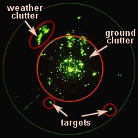
1. Sea clutter is more limited than the ground clutter, it does not cause distortions affect the target significantly from ground clutter
What you said doesn't make any sense, at all
-

- Forum Veteran

- Posts: 868
- Joined: 02 Mar 2013, 04:22
- Location: Texas
Good Grief!  This thread is STILL running?
I see the commercial RCS prediction software estimations are still making a regular appearance, (though the link provided to the source didn't work for me this one did). Pretty sure I remember this reference in a discussion on a DD1000 thread somewhere as well
This has now become a teachable moment.
The problem with estimation software (commercial or proprietary) is that it at best can only be as good as the knowledge and skill of the users. The knowledge comes from education and experience, and the skill comes from education and the ability to synthesize real-world phenomenology and theoretical science. I make no claim of either, but I have wrangled those who do.
The models and techniques used in RCS design are among the most closely held proprietary secrets in aerospace. As the government usually has at least some 'rights' to all products coming out of the materials science and overall design of weapon systems and shares it with others as circumstances demand, RCS prediction is one of a very few areas where contractors can leverage an advantage in a competition against other contractors on LO programs. The KEY to success in fielding a competent RCS design is the ability to model how your design will behave in the real-world BEFORE hardware costs pile up on what otherwise might be a dead-end. IF your predictions historically are better than the competition, and you are able to demonstrate higher fidelity predictions for critical design elements via sub-scale and partial test articles ahead of source selection you are on the winning team--as long as the rest of your design (aero performance, supportability, cost,etc) are competitive.
The analysis at the website merely illustrates the KIND of predictions that can be made, with no real provenance whatsoever for the predictions/estimations made. Further, I view the accompanying analysis with somewhat of a jaundiced eye, especially as it relates to a 'broadbrush' correlation of ship size (in tonnage) to RCS signature. That kept leaping out at me in particular because I thought I remembered something else from my past that would reject such generalization. I dig out my RCS Estimation textbook (again) and what do I find?
Thus, I could be sailing an extremely large displacement conventional hull with carefully designed superstructure and as long as I'm not orthogonal to the threat I could have a smaller RCS than a fishing boat. A DD1000 hull design (and EW) I expect pretty much takes care of the broadside problem
It should be apparent to any reasonable observer by this point that one cannot divine the RCS performance of any object merely by shape, size or surface treatment without at least tens of thousands of hours of detail design analysis, modelling and testing. So why would any reasonable person try to perpetuate a "Radar A beats LO Weapon B argument" on a board thread?
This thread is STILL running?I see the commercial RCS prediction software estimations are still making a regular appearance, (though the link provided to the source didn't work for me this one did). Pretty sure I remember this reference in a discussion on a DD1000 thread somewhere as well
This has now become a teachable moment.
The problem with estimation software (commercial or proprietary) is that it at best can only be as good as the knowledge and skill of the users. The knowledge comes from education and experience, and the skill comes from education and the ability to synthesize real-world phenomenology and theoretical science. I make no claim of either, but I have wrangled those who do.
The models and techniques used in RCS design are among the most closely held proprietary secrets in aerospace. As the government usually has at least some 'rights' to all products coming out of the materials science and overall design of weapon systems and shares it with others as circumstances demand, RCS prediction is one of a very few areas where contractors can leverage an advantage in a competition against other contractors on LO programs. The KEY to success in fielding a competent RCS design is the ability to model how your design will behave in the real-world BEFORE hardware costs pile up on what otherwise might be a dead-end. IF your predictions historically are better than the competition, and you are able to demonstrate higher fidelity predictions for critical design elements via sub-scale and partial test articles ahead of source selection you are on the winning team--as long as the rest of your design (aero performance, supportability, cost,etc) are competitive.
The analysis at the website merely illustrates the KIND of predictions that can be made, with no real provenance whatsoever for the predictions/estimations made. Further, I view the accompanying analysis with somewhat of a jaundiced eye, especially as it relates to a 'broadbrush' correlation of ship size (in tonnage) to RCS signature. That kept leaping out at me in particular because I thought I remembered something else from my past that would reject such generalization. I dig out my RCS Estimation textbook (again) and what do I find?
For all except the broadside aspect, the hull of the ship is not the dominant echo source. More important are the elements of her topside structure, not the least of which are her masts and radar antennas. --RCS Estimation, 2nd Ed. Knott et al
Thus, I could be sailing an extremely large displacement conventional hull with carefully designed superstructure and as long as I'm not orthogonal to the threat I could have a smaller RCS than a fishing boat. A DD1000 hull design (and EW) I expect pretty much takes care of the broadside problem
It should be apparent to any reasonable observer by this point that one cannot divine the RCS performance of any object merely by shape, size or surface treatment without at least tens of thousands of hours of detail design analysis, modelling and testing. So why would any reasonable person try to perpetuate a "Radar A beats LO Weapon B argument" on a board thread?
--The ultimate weapon is the mind of man.
-

- Elite 2K
- Posts: 2652
- Joined: 24 Nov 2012, 02:20
- Location: USA
My question is, has somebody ever designed a 3D projected radar screen instead of a 2D flat display?
- Forum Veteran
- Posts: 563
- Joined: 08 Feb 2011, 20:25
-

- Elite 5K

- Posts: 28404
- Joined: 05 May 2009, 21:31
- Location: Australia
That is one weird story - quoted below - cub reporters are a worry. AFAIK the RAM is built into the skin of the aircraft - not applied like paint. Sure paint is applied and here is a story about that: viewtopic.php?f=60&t=25417&p=269928&hilit=AOML#p269928 The picture below is FROM THIS STORY - see the silly captions in the story quoted below that are with some of the pics (another one below now):
I saw where the F-35 gets one of it's most classified features, and it's amazing
19 May 2015 Amanda Macias
"...“This room is the most advanced painting facility in the world,” retired US Air Force pilot and F-35 simulation instructor Rick Royer told me as we toured Lockheed Martin’s highly secure plane in Fort Worth, Texas.
The Aircraft Final Finishes bay is where America’s most expensive weapons system gets coated with a highly classified stealth technology, which makes it invisible to radar. [WRONG]
After the jet is assembled and before it can take flight, three laser-guided robots apply the “Radar-Absorbing Material” (RAM) to each of Lockheed Martin’s F-35 Lightning II variant aircrafts. [MAYBE - see below]
Here’s all we know (and can share) about how the F-35 gets it’s invisibility cloak:..." [BULLCRAP]
Source: http://www.businessinsider.com.au/where ... res-2015-5
New Stealth Concept Could Affect JSF Cost
17 May 2010 Amy Butler
"FORT WORTH — As the debate rages about Joint Strike Fighter life-cycle cost, Lockheed Martin officials are raising a previously unheard point to bolster their low-price claims — a new low-observability (LO) substance called fiber mat. Lockheed officials avoided the need to use stealthy appliqués and coatings by curing the substance into the composite skin of the aircraft, according to Tom Burbage, executive vice president of F-35 program integration for the company.
It “makes this airplane extremely rugged. You literally have to damage the airplane to reduce the signature,” he said in an interview with AVIATION WEEK. This top-fiber mat surface takes the place of metallic paint that was used on earlier stealthy aircraft designs.
The composite skin of the F-35 actually contains this layer of fiber mat, and it can help carry structural loads in the aircraft, Burbage adds. The F-35 is about 42% composite by weight, Burbage says, compared to the F-22 at 22% and the F-16 at 2%. Lockheed Martin declined to provide further details on fiber mat because they are classified...."
Source: http://www.aviationweek.com/aw/generic/ ... el=defense
Production techniques gear F-35 for stealth 2 page PDF attached
July 2006? NICK COOK JDW Aerospace Consultant
"...Visitors to the F-35 line at Fort Worth appreciate quickly how much of the production process is stealth-related. LM is responsible for the manufacture of the F-35's wing. The single wing-skin spans 42 ft (13.8 m) and high tolerances arc required in the composite build process if the aircraft's LO attributes are to be preserved.
The wing-skin is the largest composite part ever made for a fighter and represents the culmination of several decades of LM experience in composite production techniques. A key part of that experience was forged via Japan's F-2 fighter programme. Learning lessons from the F-2, a derivative of the F-16, LM was able to glean significant insights into mass-manufacture techniques for composite structures for combat aircraft. The requirement placed on the F-35 for stealth imposed an additional burden on LM to machine critical components to hair's breadth tolerances required to keep the aircraft's radar signature within the imposed design limits. Ed Linhart, vice president of the JSF production operations integrated product team, said that advances in production machinery over the past decade have allowed LM to machine the wing-skin to more than 50 microns, which, over 42 ft, has enabled him and his production team to avoid the "mismatches and gaps" that create unwanted radar reflections off the aircraft's body and surfaces.
In addition to building the F-35 for stealth, Lockheed Martin must also ensure that the aircraft is built for "supportable LO" operations. First-generation stealth aircraft like the LM F-117A and the Northrop Grumman B-2 require notorious levels of logistical support to maintain their high-stealth attributes on operations. Even the F/A-22, a generation beyond the B-2 stealth bomber, will require the application of radar-absorbent putty in gaps between skin panels to maintain its LO qualities.
According to Linhart. the F-35 cannot afford to be "swarmed over by Martians", a nickname for stealth maintainers, when it is deployed on operations. This has imposed a requirement on LM and its partners to adopt techniques in the production process that will ensure ease of stealth maintenance in the field.
In addition to machining advances that allow LM to achieve high manufacturing tolerances, advances have also been made in the composition of the radar-absorbent structure (RAS) of the aircraft. This, Linhart said, is "completely different" from earlier RAS materials in the way it is resistant to chipping, even in the face of bird-strikes....
...After the mated section of the aircraft - forward fuselage, wing and rear fuselage - have left the moving assembly line they are wheeled into a painting and coatings facility where LO treatments are applied - this, after an earlier set of coatings has been applied to the wings, fuselage and control surfaces. The aircraft and its electronics are then measured for stealth within a radar cross-section and emissions facility close to the production line...."
Source: http://www.navy.mi.th/nrdo/jane/dev_w/p ... July48.pdf [no longer there]
- Attachments
-
- F-35robotPaintCellAOML.jpg (103.68 KiB) Viewed 25093 times
-
 JSF Making Stealth productionJuly48 TEXT READABLE.pdf
- (760.98 KiB) Downloaded 1255 times
-
- Senior member

- Posts: 403
- Joined: 04 Feb 2015, 22:03
This sounds like the confusion amongst reporters about what Thermion really does (It's magically delicious!)
Isn't the point of all this robotic painting to ensure that the RCS doesn't go UP when paint is applied? As mentioned in one article, the actual RAM material is part of the composite skin. It would seem the need for the fancy painting is so you get an amazingly thin and even coat of paint. It would seem that if paint were applied in varying amounts or there were globs of it built up around seams, you can raise the RCS, albeit by tiny amounts, but the goal is to reduce radar return in every possible manner. A few thousandths of a point could mean a big difference in survival when two planes are on intercept tracks and the F-35 has fired off a missile. A couple of kilometers of additional radar range for the target's avionics could be the difference between starting the lock-on process and actually dropping a missile off a rail.
Isn't the point of all this robotic painting to ensure that the RCS doesn't go UP when paint is applied? As mentioned in one article, the actual RAM material is part of the composite skin. It would seem the need for the fancy painting is so you get an amazingly thin and even coat of paint. It would seem that if paint were applied in varying amounts or there were globs of it built up around seams, you can raise the RCS, albeit by tiny amounts, but the goal is to reduce radar return in every possible manner. A few thousandths of a point could mean a big difference in survival when two planes are on intercept tracks and the F-35 has fired off a missile. A couple of kilometers of additional radar range for the target's avionics could be the difference between starting the lock-on process and actually dropping a missile off a rail.
-

- Forum Veteran
- Posts: 716
- Joined: 28 Dec 2011, 05:37
- Location: CA
The accident investigation for the engine fire thread: from viewtopic.php?f=22&t=25667&start=465#
provided us an interesting view of the differences in thickness of the RAM coatings from Top fuselage panels to Side fuselage panels.
You can also observe what appears to be the upper surface panel's underlying material apparently devoid of damaged RAM material almost entirely?
NOTE: Lots of speculation here. It is also possible that the heat of the event caused the RAM layers to separate and loose adherence/bonding. That would cause the RAM to only look like it is very thick in some places.
provided us an interesting view of the differences in thickness of the RAM coatings from Top fuselage panels to Side fuselage panels.
You can also observe what appears to be the upper surface panel's underlying material apparently devoid of damaged RAM material almost entirely?
- ScreenHunter_01 Jun. 08 16.20.jpg (60.01 KiB) Viewed 24400 times
NOTE: Lots of speculation here. It is also possible that the heat of the event caused the RAM layers to separate and loose adherence/bonding. That would cause the RAM to only look like it is very thick in some places.
Daddy why do we have to hide? Because we use VI son, and they use windows.
- Elite 2K
- Posts: 2561
- Joined: 12 Jan 2014, 19:26
I read this for S&Gs...
http://aviationweek.com/blog/behind-f-3 ... bat-report
Here Bill Sweetman AKA BS is trying to shovel more of his BS (bovine fecal matter). Of course the tard is going to misconstrue certain things to push his agenda. he wouldn't be a good reformer if he didn't. Then I came across this part...
I have no doubt that even with 2 external sidewinders the F-35 would still be stealthy. Even the B and C variants with external sidewinders and it's gunpod, the F-35 would still be considerably more stealthy then current fighter aircraft. I have debated this point with others . Though I do wonder, how much of an impact would 2 sidewinders and an its external gun pod have on the F-35?
http://aviationweek.com/blog/behind-f-3 ... bat-report
Here Bill Sweetman AKA BS is trying to shovel more of his BS (bovine fecal matter). Of course the tard is going to misconstrue certain things to push his agenda. he wouldn't be a good reformer if he didn't. Then I came across this part...
Unlike the F-22 (and the Chengdu J-20 and Sukhoi T-50) it doesn't have side bays and trapezes for rail-launched AAMs. If the F-35 carries AIM-9s it does so externally, and by Lockheed Martin's own definition it is not stealthy.
I have no doubt that even with 2 external sidewinders the F-35 would still be stealthy. Even the B and C variants with external sidewinders and it's gunpod, the F-35 would still be considerably more stealthy then current fighter aircraft. I have debated this point with others
. Though I do wonder, how much of an impact would 2 sidewinders and an its external gun pod have on the F-35?- Enthusiast

- Posts: 80
- Joined: 12 Dec 2013, 17:36
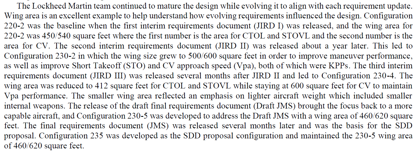
Hey guys, recently I receive some information of JSF program from others. One is a picture comes from LM's paper ("F-35 Program History – From JAST to IOC") which shows that during the development of JSF projram (before SDD phase), there probably had a requirement for low band RCS reduction. (Highlighted with a red box in the figure )
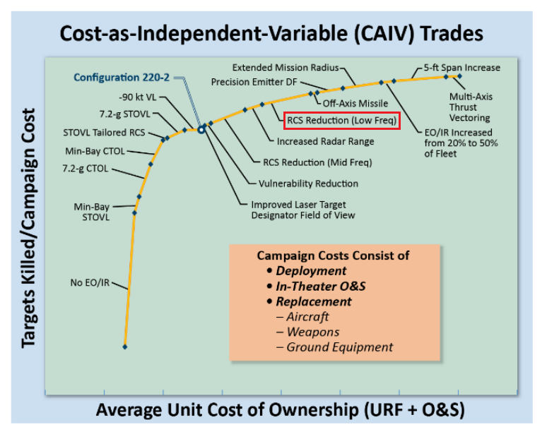
Also, there was an article published on Aviation Week in 1999/2, "JSF Reflection Is Golf Ball-Sized", which not only stated that the requirement of the RCS spec. for JSF was -30 db but also mentioned that the JSF would have the low-observability ability in VHF band. So it seems like the military, at least, had once considered the VHF RCS reduction for the JSF program (maybe happened at JIRD-1 or -2 or -3 ? Configuration 220-2 was the baseline design when JIRD-1 was released.). Do you guys have any further information about this or whether this low band RCS reduction requirement was retained or dropped after the program entered SDD phase ?
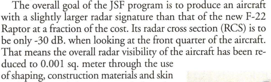
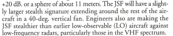
PS. what does "in a 40-deg. vertical fan" mean in the picture ?
Does there have any report or rumor mentioned the JSF RCS spec. earlier than that article (1999/2) ?
Also, there was an article published on Aviation Week in 1999/2, "JSF Reflection Is Golf Ball-Sized", which not only stated that the requirement of the RCS spec. for JSF was -30 db but also mentioned that the JSF would have the low-observability ability in VHF band. So it seems like the military, at least, had once considered the VHF RCS reduction for the JSF program (maybe happened at JIRD-1 or -2 or -3 ? Configuration 220-2 was the baseline design when JIRD-1 was released.). Do you guys have any further information about this or whether this low band RCS reduction requirement was retained or dropped after the program entered SDD phase ?
PS. what does "in a 40-deg. vertical fan" mean in the picture ?
Does there have any report or rumor mentioned the JSF RCS spec. earlier than that article (1999/2) ?
Last edited by taog on 10 Jun 2019, 03:23, edited 1 time in total.
-
- Elite 2K
- Posts: 2361
- Joined: 27 Mar 2015, 16:05
taog wrote:Hey guys, recently I receive some information of JSF program from others. One is a picture comes from LM's paper ("F-35 Program History – From JAST to IOC") which shows that during the development of JSF projram (before SDD phase), there had a requirement for low band RCS reduction. (Highlighted with a red box in the figure )
Also, there was an article published on Aviation Week in 1999/2, "JSF Reflection Is Golf Ball-Sized", which not only stated that the requirement of the RCS spec. for JSF was -30 db but also mentioned that the JSF would have the low-observability ability in VHF band. So it seems like the military, at least, had once considered the VHF RCS reduction for the JSF program (maybe happened at JIRD-1 or -2 or -3 ? Configuration 220-2 was the baseline design when JIRD-1 was released.). Do you guys have any further information about this or whether this low band RCS reduction requirement was retained or dropped after the program entered SDD phase ?
PS. what does "in a 40-deg. vertical fan" mean in the picture ?
Does there have any report or rumor mentioned the JSF RCS spec. earlier than that article (1999/2) ?
Great info, would you mind screenshot or cite the source?
- Enthusiast
- Posts: 80
- Joined: 12 Dec 2013, 17:36
eloise wrote:taog wrote:Hey guys, recently I receive some information of JSF program from others. One is a picture comes from LM's paper ("F-35 Program History – From JAST to IOC") which shows that during the development of JSF projram (before SDD phase), there had a requirement for low band RCS reduction. (Highlighted with a red box in the figure )
Also, there was an article published on Aviation Week in 1999/2, "JSF Reflection Is Golf Ball-Sized", which not only stated that the requirement of the RCS spec. for JSF was -30 db but also mentioned that the JSF would have the low-observability ability in VHF band. So it seems like the military, at least, had once considered the VHF RCS reduction for the JSF program (maybe happened at JIRD-1 or -2 or -3 ? Configuration 220-2 was the baseline design when JIRD-1 was released.). Do you guys have any further information about this or whether this low band RCS reduction requirement was retained or dropped after the program entered SDD phase ?
PS. what does "in a 40-deg. vertical fan" mean in the picture ?
Does there have any report or rumor mentioned the JSF RCS spec. earlier than that article (1999/2) ?
Great info, would you mind screenshot or cite the source?
Just do it.
Who is online
Users browsing this forum: No registered users and 2 guests